NRG Link Gas Boiler – Solid Fuel Stove – DHW 2x Radiators
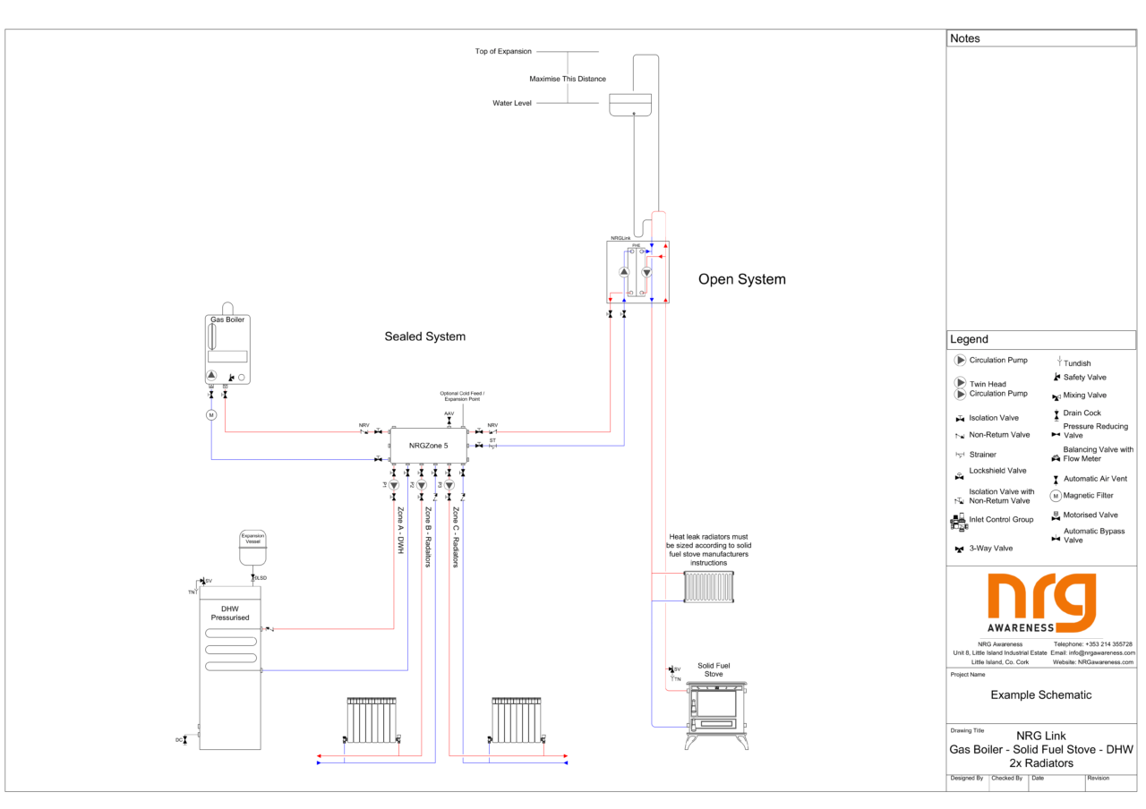
This schematic shows a dual-pressure heating system with a sealed gas boiler and an open vented solid fuel stove. There are 3 zones, 1 DHW zone and two radiator zones, all on the sealed side of the system. The DHW cylinder has a non-return valve on the flow into the coil instead of on the return like the heating zones, this is to prevent heat drifting from the cylinder, through the coil and up into the NRG Zone when the zone is not on. The solid fuel stove has an open gravity circuit rising up from the stove, through the fully open primary pipes in the NRG Link and back down to the stove. There is a heat leak radiator on the return pipe to dissipate any excess heat from the stove in the event of a power outage. This primary circuit is crucial for the safety of the system and there can be no valves or restriction on it. When the stove is lit, the hot water will rise there will be circulation in the primary pipes. When the thermostat in the NRG Link detects that the stove is up to temperature the two pumps in the NRG Link will run. One pump will take hot water from the primary circuit through a plate heat exchanger in a parallel circuit, the other pump will circulate the water from the NRG Zone through the other side of the plate heat exchanger to transfer the heat from the open system to the sealed system. There is a strai
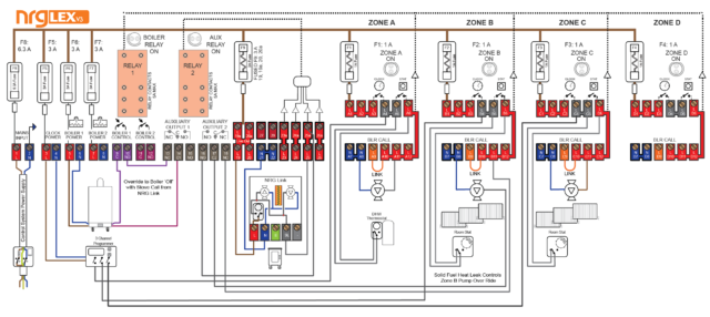
The system is wired in such a way that whenever the NRG Link is running, meaning the stove is hot, the gas boiler circuit will be broken and Zone B will turn on as a heat leak zone to dissipate the heat from the stove and prevent it from overheating. Zone A and Zone C will continue to work as normal using their time and temperature controls. When the NRG Link is running there is a switch-live coming from it into terminal 25. When there is a live signal at terminals 23-26 the switches on auxiliary outputs 1 and 2 will switch from normally closed (NC) to normally open (NO). For auxiliary output 1 this means that the connections between terminals 13 and 14 are broken, preventing the gas boiler from turning on. For auxiliary output 2 this means that the connections between terminals 16 and 17 are made, meaning that the switch live signal coming from the NRG Link into 25 through 25a can pass from 18 through 17 and run the Zone B pump. When the NRG Link is not running, conncetions 17 and 18 are made so the Zone B pump is controlled by the normal zone controls coming from B11 through 18 and out of 17 to run the pump.